YardShape™ 4 in 1 Extended Reach Multi-Cutter Expanded Manual
1)
Connecting Tube Sections Reducing
Extension Length
2) Mixing Fuel and Starting
3) Starting Part 2
4) Carburator Adjustment
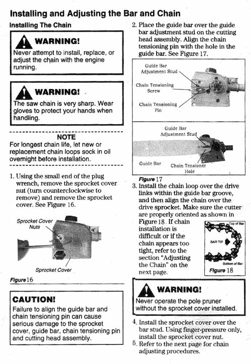
5) Chainsaw Bar and Chain Installation
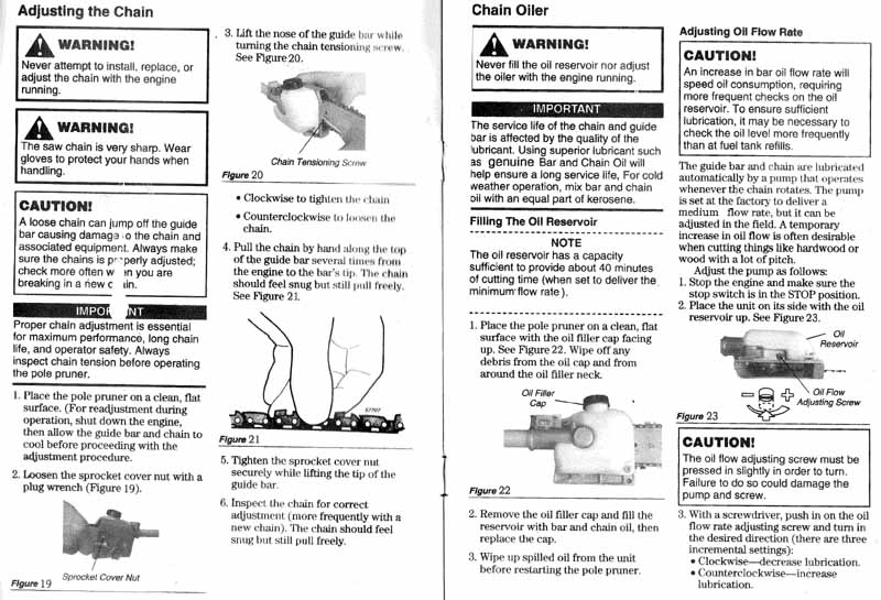
6) Chain Adjustment and Oiling
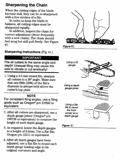
7) Chain Sharpening
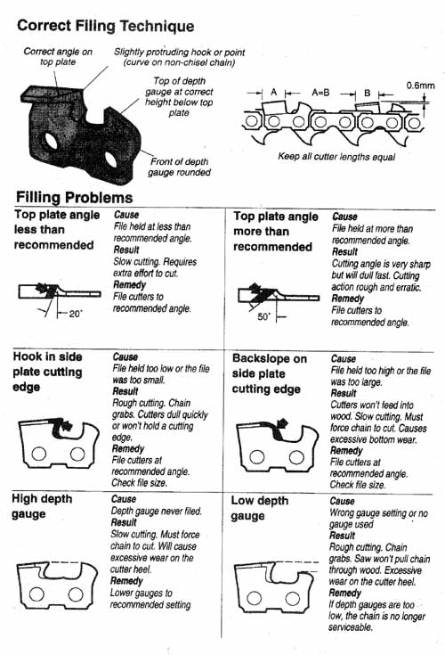
8) Chain Filing
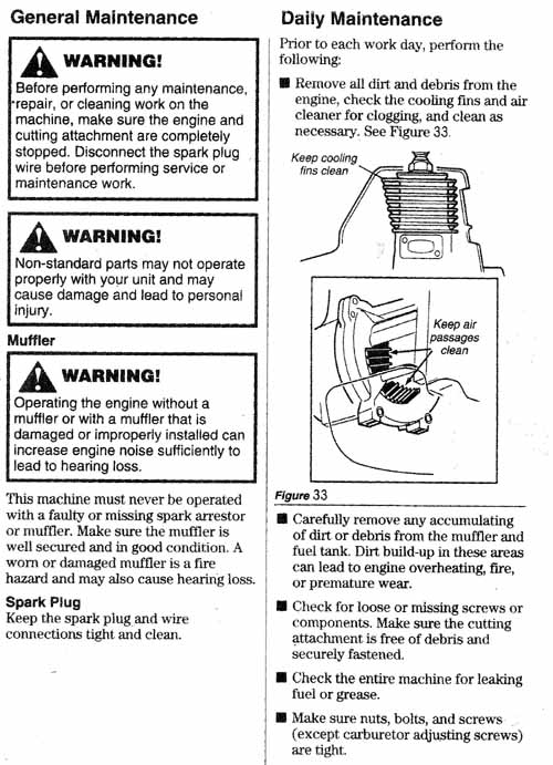
9) Maintenance - Daily
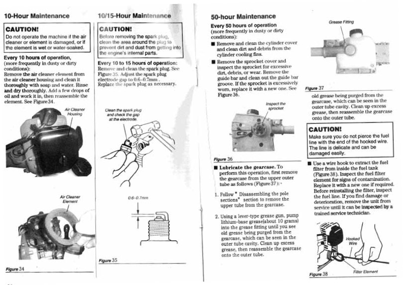
10) Maintenance 10 to 50 hours
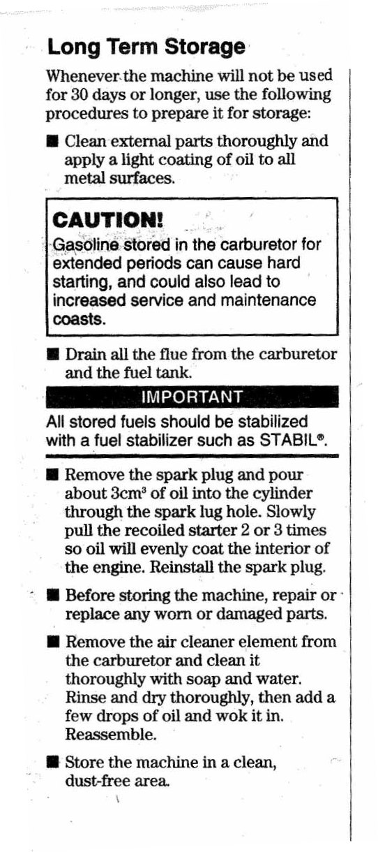
11) Storage Long Term
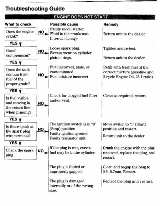
12) Troubleshooting and Known Issues
13)
Specifications
14) CE Standards Certificate
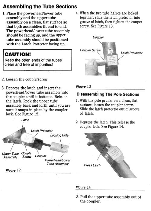
Assembling the sections Back to top
Fuel & Starting Part 1 Back to top
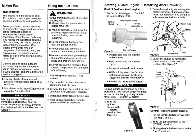
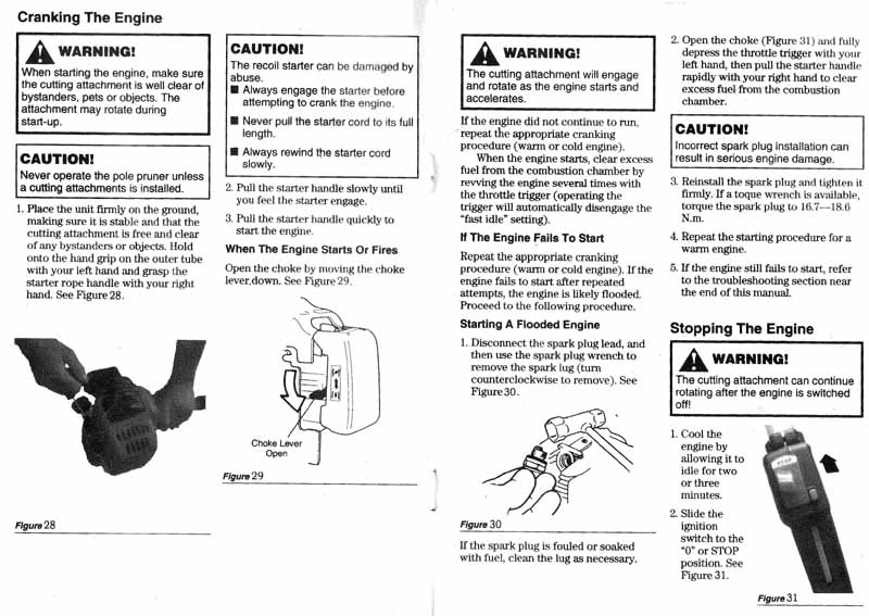
Fuel and Starting Part 2 Back to top
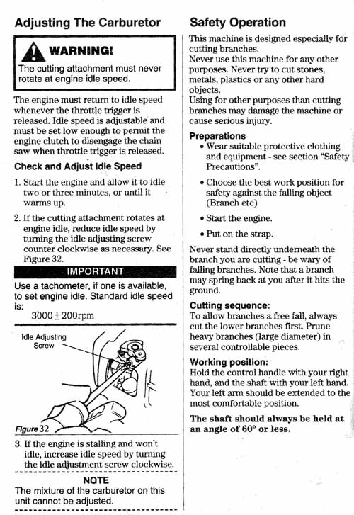
Carburator Adjustment Back to top
Chain Installation Back to top
Chain adjustment and oiling Back to top
Chain Sharpening Back to top
Carlton #N1 Chain Details: http://www.sawchain.com/images/2008-2009 Intl Catalog/filingSpec.pdf
Pitch: 3/8”/ Gauge: .050”/ Side plate angle: 85°-90° / Top plate cutting angle: 60°/ Top plate filing angle: 35°/ File angle: 90°/ Carlton File Tool Number: 65993/ File Size: 5/32" or 4.0mm
Chain Filing Back to top
Daily Maintenance Back to top
Maintenance 10 to 50 hours Back to top
Long Term Storage Back to top
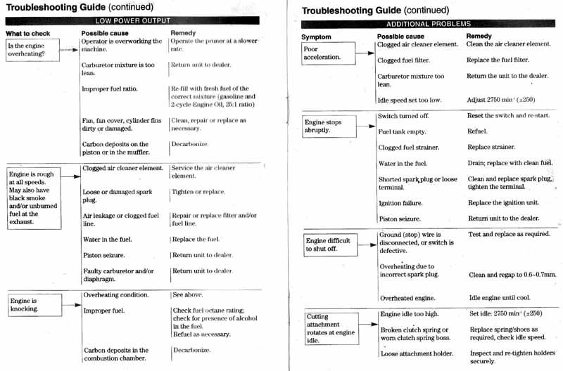
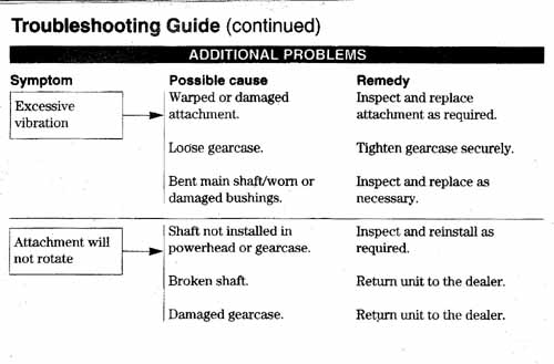
Trouble Shooting and Known Issues Back to top See Trouble chart Below
The following are some simple fixes for some issues we have had on a few units.
1) Cannot get Attachment Tube to Click in Coupler. With brand new units it may be difficult to get the latch in the coupler on the power unit to click into the "click" hole on the attachment tube. You may find that it is not necessary to push the tube all the way into the coupler to get them clicked. Gently rotate and move in/out to feel where the latch will click. If the tube is pushed all the way into the coupler, and it is still not engaging, try rotating the tube from side to side a few times. When you pull out the tube again, you should see a little mark where the latch point was rubbing on the tube to give you a idea of where the hole on tube should be adjusted to. You can take a thin round file and gently file the edges of the click hole on the attachment tube see picture This connection will get easier as you use the unit. Do not use the heads until you have the latch on the coupler engaged in the hole on the tube.
3) Hedge Trimmer Blades do not move but engine
can get to full revs. When using your hedge trimmer check to make sure
that the nut with cotter pin securing the bolt going through the articulating
elbow joint is not backing off or loose, and the the 2 joint halves are firmly
seated. If the nut is not gently tightened up to eliminate play, the 2 halves of
the joint can start to move away from each other and the gears inside can lose
contact. A simple solution is to remove the cotter pin and tighten the nut by
one space, or put a few washers under the nut to reduce the play. You can also
put a 6mm (M6) lock nut (available at Home Depot, Rona, or similar for 30 cents)
on top of the existing nut and cotter pin (see photo), or just remove the
existing nut and cotter pin and replace with a lock washer and the M6 lock nut.
Tighten the nut enough to eliminate play but do not over tighten.
4) Hedge Trimmer Blades do not move and engine is bogging down.
This is probably because some or all of the 3 bolts/nuts that hold your hedge
trimmer blades together are too tight. The washers on the bolt head side should
feel loose enough that they can be turned by hand. If the washers do not spin,
you will have to loosen the bolt. First, back off the nut by a turn. Then on the
other side of the blade, use a large phillips driver or vise grips to back off
the bolt head by a half turn. If the washers are loose, the bolt head position
is good. While holding the bolt head from moving, re-snug the nut, and then
re-check to the see that the washers will still spin. Basically, the idea is to
have a small space between washers and blade on the bolt head side to allow the
blades some room to slide against each other.
4) Hedge trimmer blade bolts getting loose. Some units do not have 6mm lock nuts on the hedge trimmer blade bolts. Simply replace the nut with a lock nut (6mm) or put some thread lock compound on the threads and refasten the existing nuts.
5) Power Head Play. The engine head is attached to the tubing with a special rubber bushing (inside cone shaped clutch housing). The bushing is designed to dampen rotational force as you power up from idle to full speed and ease stress on the components. The engine head may rotate slightly on the tube as you throttle up. This is NORMAL and a function of the design. If you are concerned, click here.
6) Cannot Open Line Trimmer Spool. Read the section on replacing trimmer line here.
7) Engine will not turn over (locked). Some units may feel like the engine is locked and the pull chord is stuck. This is a very simple fix. Click here for solution.
8) Handle base is cracked. The handle base can crack if the 4 bolts are not tightened evenly. The base can be easily replaced with straps. See http://multipowertools.com/support/handlebase/ for details
9) Pull Start Unit not retracting (G2). See solution at http://multipowertools.com/support/pullg2/index.htm
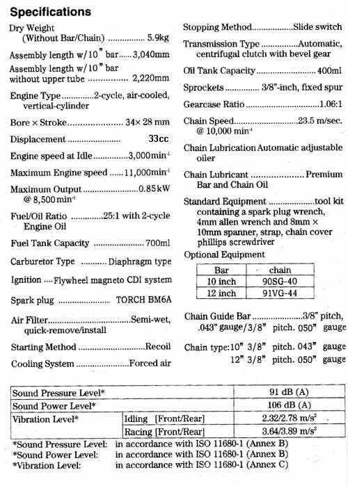
Specifications Back to top
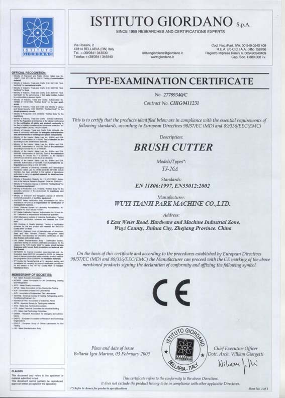
CE Standards Certificate Back to top
The coupler on the power unit can be removed, and a gear case from one of the attachments can be attached directly on the power unit if you need shorter length. Of course you cannot do a quick change without the coupler, but you can put it back on later. There is just 2 bolts to remove on the coupler, and the bolt configuration on the attachment gear cases is basically the same. Takes 10 minutes if you are handy. Sometimes the through-tube bolt hole on the power unit does not line up perfectly with the attachment gear case bolt hole, so you may have to re-drill a new through-tube hole, but this does not affect operation or replacement of the coupler.